
It all started with something simple: my battery-powered Christmas LED lights. I loved how they looked, but I wanted to make them more convenient by powering them through USB instead of burning through AA batteries. Simple idea, right?
So, I grabbed a USB cable, did some basic soldering, and connected the 5V to where the batteries used to be. The result?
Only half the LEDs lit up.
Weird. I thought maybe there was a bad connection. I double-checked everything, flipped the polarity… and then something strange happened: the other half lit up. That’s when I realized — these LEDs are wired in a special way. One set lights up with one polarity, the other lights up with the opposite. They were alternating: A-B-A-B-A-B all the way down the strip.
I needed a way to switch polarity back and forth really fast.
Enter the concept of an H-bridge. I found out that an H-bridge circuit can reverse the direction of current through a load. It was originally meant for controlling motors, but it would work perfectly for toggling the polarity on my LEDs. I settled on using a DRV8833 motor driver chip for the job.
But now I had a new problem — the H-bridge needs two input signals (IN1 and IN2), and they need to be the exact opposite of each other. If IN1 is HIGH and IN2 is LOW, current flows one way. Reverse them, and current flows the other way. So I needed a way to generate an alternating signal — something that goes HIGH and LOW repeatedly at a fast pace.
Time to meet the NE555P timer.
This little chip can output a square wave — a perfect on/off signal that flips continuously. I wired it in astable mode to generate a continuous square wave and fed its output into IN1 of the H-bridge.
Now I needed to invert the signal for IN2. I used a simple NPN transistor (2N2222) to act as an inverter. When the timer output was HIGH, the transistor pulled IN2 LOW. When the timer was LOW, a pull-up resistor brought IN2 HIGH. Success — both inputs were now always opposite.
The lights started blinking! But not the way I wanted — one side stayed lit longer than the other. That led me down a rabbit hole of understanding the duty cycle of the NE555 — the ratio between ON time and OFF time. In its basic configuration, the 555 spends more time HIGH than LOW. To fix that, I added a diode across one of the resistors to allow the capacitor to charge through one resistor and discharge through another, balancing the ON/OFF time.
I also added decoupling capacitors for stability and a current-limiting resistor in series with the LEDs.
Finally, everything clicked.
The Circuit Explained


NE555 Timer Section (U2):
- The heart of the timing. It’s configured in astable mode, meaning it continually switches between HIGH and LOW.
- R1 and R2 set the timing, and C2 (the timing capacitor) controls how fast the signal toggles.
- D1 (diode) allows the capacitor to charge through R1 and discharge through R2, balancing the ON/OFF times to achieve a near 50% duty cycle.
- C3 (on pin 5) stabilizes the internal voltage divider inside the 555. C1 is a decoupling capacitor.
Understanding C2’s Role (Timing Capacitor):
- C2 charges up through R1. While charging, the voltage across it rises.
- When it hits 2/3 of the supply voltage, the 555 flips its output LOW and internally connects pin 7 (DISCH) to ground.
- This discharges C2 through R2. When the voltage falls below 1/3 of the supply voltage, the 555 flips its output HIGH again.
- This loop repeats, forming a square wave.
- So pin 7 acts like an internal switch to GND during discharge, and disconnects during charging.
Inverter Section (T1):
- A 2N2222 NPN transistor.
- Base connected to the NE555 output via resistor R3.
- Collector goes to IN2 of the H-bridge, with a pull-up resistor R4 to VCC.
- Emitter goes to GND.
- This ensures IN2 is always the opposite of IN1.
H-Bridge Section (DRV8833):
- Takes IN1 and IN2 as inputs.
- OUT1 and OUT2 switch polarity based on those inputs.
- EEP pin is tied to VCC so the chip is always enabled.
LED Strip:
- Connected between OUT1 and OUT2.
- With alternating polarity, both A and B LEDs blink so fast they appear always on.
Final Touches:
- A 50-ohm resistor between one driver output and the LED strip limits current.
- C4 is another decoupling capacitor near the driver chip.
What I Learned
- Mistakes teach best: I wired the transistor backward. I forgot the pull-up. I flipped the diode.
- Understanding the 555’s internal workings gave me real insight — not just how to build the circuit, but why it works.
- It’s not about blindly following a diagram. It’s about learning to see how each part contributes to the system.

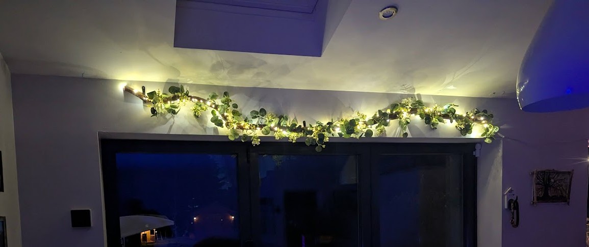
As a final touch, I have made a socket for C2 so it can be swapped, for experimenting with different frequencies. After some trial and error I figured that 0.47uF works best to simuilated steady on without noticing any flickering – exactly what I wanted.
This was one of those projects where I came for a quick fix, and stayed for the rabbit hole. And now I’ve got a beautifully working, USB-powered LED strip and my own mini-board that I can easily replicate for my next LED strip (apparently these types of LED strips are very common, and super cheap).
Leave a Reply